
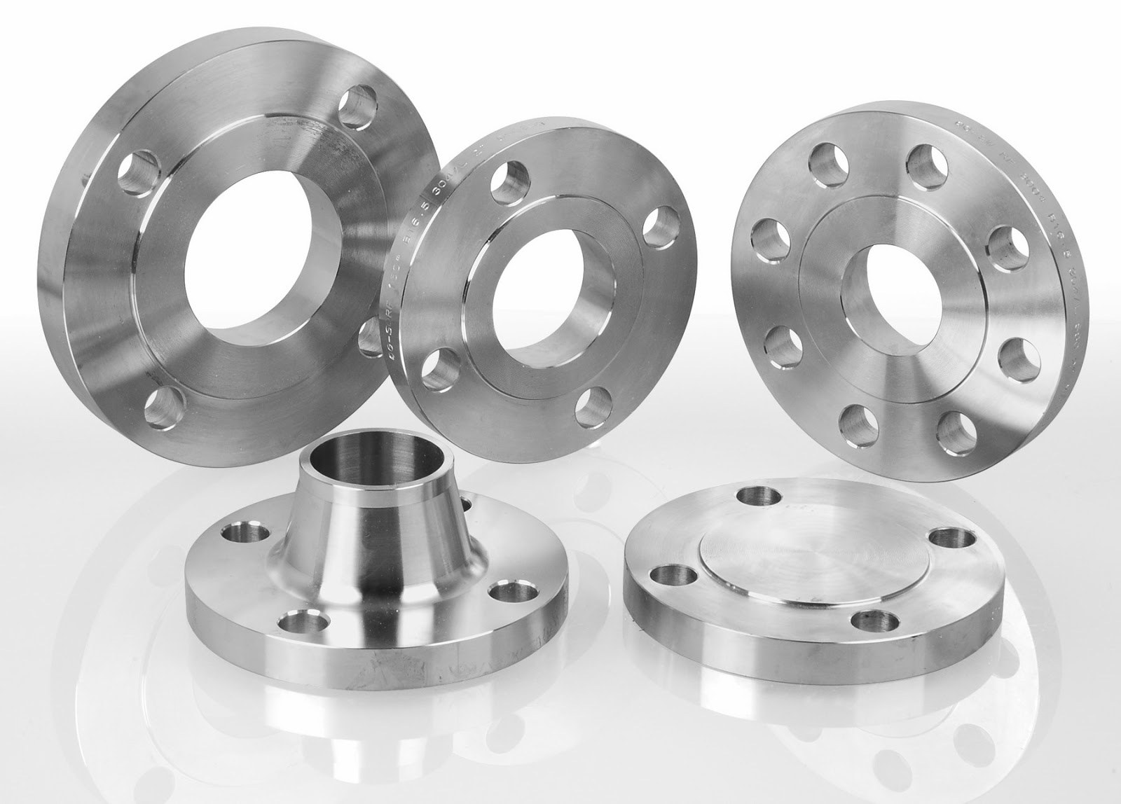
Stainless Steel Flanges
S tainless Steel Flanges are made up of different stainless steel materials. There are different grades to the stainless steel depending on the material composition and the mechanical properties vary.SS Flanges aid in connecting pipes, valves, pumps and other equipment to pipes. Besides acting as a mediator or a connector, the Stainless Steel Header Flanges also provide easy access when they have to be cleaned, inspected or modified. Stainless Steel Exhaust Flanges have been designed to interface sections of pipe whilst enabling their easy assembly and disassembly. Usually Stainless Steel Split Flanges are an external or internal ridge, or rim.
A Stainless Steel Compression Fittings is a kind of versatile coupling which can be used to connect two pipes or a pipe to either a fixture or a valve. The SS Twin Ferrule Compression Fittings consists of three parts. The compression nut along with the compression ring and the compression seat is a part of the Hydraulic Compression Fittings.
Standard Specification Of Flanges
| Stainless Steel Flanges Specifications | ASTM A182 / ASME SA182 |
|---|---|
| Size Chart of SS Blind Flanges | 1/2″ (15 NB) to 48″ (1200NB) |
| Standards Of ASTM A182 Stainless Steel Slip on flanges |
ANSI/ASME B16.5, B 16.47 Series A & B, B16.48, BS4504, BS 10, EN-1092, DIN, etc. |
| Class / Pressure rating of SS WN flanges | 150#, 300#, 600#, 900#, 1500#, 2500#, PN6, PN10, PN16, PN25, PN40, PN64 etc. |
| American Standard of SS Flanges | ANSI Flanges, ASME Flanges, BS Flanges, DIN Flanges, EN Flanges, etc. |
Martensitic Stainless Steel Exhaust Flange Size in mm
Nominal Pipe Size
Outside Diameter of Flanges
Thickness of Flanges
Diameter of Raised Face
Diameter of Hub at Base
Length Thru Hub
Diameter or Bore
Diameter of Hub at Bevel
Radius of Fillet
Depth of Socket
Welding Neck
Slip-On Threaded Socket
Lap Joint
Slip-on Socket
Lap Joint
O
Q
R
X
Y
Y
Y
W
B
H
r
Z
1/2
3-1/2
7/16
1-3/8
1-3/16
1-7/8
5/8
5/8
.88
.90
.84
1/8
3/8
3/4
3-7/8
1/2
1-11/16
1-1/2
2-1/16
5/8
5/8
1.09
1.11
1.05
1/8
7/16
1
4-1/4
9/16
2
1-15/16
2-3/16
11/16
11/16
1.36
1.38
1.32
1/8
1/2
1-1/4
4-5/8
5/8
2-1/2
2-5/16
2-1/4
13/16
13/16
1.70
1.72
1.66
3/16
9/16
1-1/2
5
11/16
2-7/8
2-9/16
2-7/16
7/8
7/8
1.95
1.97
1.90
1/4
5/8
2
6
3/4
3-5/8
3-1/16
2-1/2
1
1
2.44
2.46
2.38
5/16
11/16
2-1/2
7
7/8
4-1/8
3-9/16
2-3/4
1-1/8
1-1/8
2.94
2.97
2.88
5/16
3/4
3
7-1/2
15/16
5
4-1/4
2-3/4
1-3/16
1-3/16
3.57
3.60
3.50
3/8
13/16
3-1/2
8-1/2
15/16
5-1/2
4-13/16
2-13/16
1-1/4
1-1/4
4.07
4.10
4.00
3/8
7/8
4
9
15/16
6-3/16
5-5/16
3
1-5/16
1-5/16
4.57
4.60
4.50
7/16
15/16
5
10
15/16
7.5/16
6-7/16
3-1/2
1-7/16
1-7/16
5.66
5.69
5.56
7/16
15/16
6
11
1
8-1/2
7-9/16
3-1/2
1-9/16
1-9/16
6.72
6.75
6.63
1/2
1-1/16
8
13-1/2
1-1/8
10-5/8
9-11/16
4
1-3/4
1-3/4
8.72
8.75
8.63
1/2
1-1/4
10
16
1-3/16
12-3/4
12
4
1-15/16
1-15/16
10.88
10.92
10.75
1/2
1-5/16
12
19
1-1/4
15
14-3/8
4-1/2
2-3/16
2-3/16
12.88
12.92
12.75
1/2
1-9/16
14
21
1-3/8
16-1/4
15-3/4
5
2-1/4
3-1/8
14.14
14.18
14.00
1/2
1-5/8
16
23-1/2
1-7/16
18-1/2
18
5
2-1/2
3-7/16
16.16
16.19
16.00
1/2
1-3/4
18
25
1-9/16
21
19-7/8
5-1/2
2-11/16
3-13/16
18.18
18.20
18.00
1/2
1-15/16
20
27-1/2
1-11/16
23
22
5-11/16
2-7/8
4-1/16
20.20
20.25
20.00
1/2
2-1/8
24
32
1-7/8
27-1/4
26-1/8
6
3-1/4
4-3/8
24.25
24.25
24.00
1/2
2-1/2
Stainless Steel Slip On Flange Chemical Structure
Type
C
Mn
P
S
Si
Cr
Ni
Mb
302
0.15
2.00
0.045
0.030
1.00
17.00/19.00
8.00/10.00
–
304
0.08
2.00
0.045
0.030
1.00
18.00/20.00
8.00/10.50
–
304L
0.03
2.00
0.045
0.030
1.00
18.00/20.00
8.00/12.00
–
309
0.20
2.00
0.045
0.030
1.00
22.00/24.00
12.00/15.00
–
309S
0.08
2.00
0.045
–
1.00
22.00/24.00
–
–
310
0.25
2.00
0.045
0.030
1.5
24.00/26.00
19.00/22.00
–
310S
0.08
2.00
0.045
0.030
1.5
24.00/26.00
19.00/22.00
–
316
0.08
2.00
0.045
0.030
1.00
16.00/18.00
10.00/14.00
2.00/3.00
316L
0.03
2.00
0.045
0.030
1.00
16.00/18.00
10.00/14.00
2.00/3.00
317
0.08
2.00
0.045
0.030
1.00/1.00
18.00/20.00
11.00/15.00
3.00/4.00
317L
0.03
2.00
0.045
0.030
0.75
18.00/20.00
11.00/15.00
3.00/4.00
321
0.08
2.00
0.040
0.030
1.00
17.00/19.00
9.00/12.00
0.75/0.75
347
0.08
2.00
0.040
0.030
0.5/1.00
17.00/19.00
9.00/12.00
0.5/0.75
Application Of SS Flanges
-
-
-
-
-
Features Of SS Fittings 304/316
-
-
-
-
Types of Stainless Steel Flanges
ASTM A105N Blind Flange, BS EN 10204-3.1, 2 Inch, Class 600, RF
ASTM A182 Lapped Joint Flanges, 1 Inch, ANSI B16.5
SS Orifice Flanges, A182 3 In, Class 300, SCH 40, Raised Face
ASTM A350 LF2 Blind Spade Flanges, ASME B16.5, 2 Inch, Class 300
ASME SA-516 Grade 70, OD 2876.55*ID 2514.6 MM
ASTM A182 SW Flanges, Class 150, 2 Inch, SCH 40, RF
SS Threaded Flanges, 150 LB, 1/2IN, RF
ASTM A182 WN Flanges, 10 Inch, Class 150 LB, SCH 40
Forged Steel Nipoflange, 3 Inch, Class 300, API
EN 1092-1 GP240GH Flat Plate Flanges, PN16, DN100
Forged Stainless Steel Flange, 12 Inch, Class D
ASTM A182 Plate Flange, PN 16, DN 125

Stainless Steel 304 Flanges
| Nominal Pipe Size | Outside Diameter of Flanges | Thickness of Flanges | Diameter of Raised Face | Diameter of Hub at Base | Length Thru Hub | Diameter or Bore | Diameter of Hub at Bevel | Radius of Fillet | Depth of Socket | |||
|---|---|---|---|---|---|---|---|---|---|---|---|---|
| Welding Neck | Slip-On Threaded Socket | Lap Joint | Slip-on Socket | Lap Joint | ||||||||
| O | Q | R | X | Y | Y | Y | W | B | H | r | Z | |
| 1/2 | 3-1/2 | 7/16 | 1-3/8 | 1-3/16 | 1-7/8 | 5/8 | 5/8 | .88 | .90 | .84 | 1/8 | 3/8 |
| 3/4 | 3-7/8 | 1/2 | 1-11/16 | 1-1/2 | 2-1/16 | 5/8 | 5/8 | 1.09 | 1.11 | 1.05 | 1/8 | 7/16 |
| 1 | 4-1/4 | 9/16 | 2 | 1-15/16 | 2-3/16 | 11/16 | 11/16 | 1.36 | 1.38 | 1.32 | 1/8 | 1/2 |
| 1-1/4 | 4-5/8 | 5/8 | 2-1/2 | 2-5/16 | 2-1/4 | 13/16 | 13/16 | 1.70 | 1.72 | 1.66 | 3/16 | 9/16 |
| 1-1/2 | 5 | 11/16 | 2-7/8 | 2-9/16 | 2-7/16 | 7/8 | 7/8 | 1.95 | 1.97 | 1.90 | 1/4 | 5/8 |
| 2 | 6 | 3/4 | 3-5/8 | 3-1/16 | 2-1/2 | 1 | 1 | 2.44 | 2.46 | 2.38 | 5/16 | 11/16 |
| 2-1/2 | 7 | 7/8 | 4-1/8 | 3-9/16 | 2-3/4 | 1-1/8 | 1-1/8 | 2.94 | 2.97 | 2.88 | 5/16 | 3/4 |
| 3 | 7-1/2 | 15/16 | 5 | 4-1/4 | 2-3/4 | 1-3/16 | 1-3/16 | 3.57 | 3.60 | 3.50 | 3/8 | 13/16 |
| 3-1/2 | 8-1/2 | 15/16 | 5-1/2 | 4-13/16 | 2-13/16 | 1-1/4 | 1-1/4 | 4.07 | 4.10 | 4.00 | 3/8 | 7/8 |
| 4 | 9 | 15/16 | 6-3/16 | 5-5/16 | 3 | 1-5/16 | 1-5/16 | 4.57 | 4.60 | 4.50 | 7/16 | 15/16 |
| 5 | 10 | 15/16 | 7.5/16 | 6-7/16 | 3-1/2 | 1-7/16 | 1-7/16 | 5.66 | 5.69 | 5.56 | 7/16 | 15/16 |
| 6 | 11 | 1 | 8-1/2 | 7-9/16 | 3-1/2 | 1-9/16 | 1-9/16 | 6.72 | 6.75 | 6.63 | 1/2 | 1-1/16 |
| 8 | 13-1/2 | 1-1/8 | 10-5/8 | 9-11/16 | 4 | 1-3/4 | 1-3/4 | 8.72 | 8.75 | 8.63 | 1/2 | 1-1/4 |
| 10 | 16 | 1-3/16 | 12-3/4 | 12 | 4 | 1-15/16 | 1-15/16 | 10.88 | 10.92 | 10.75 | 1/2 | 1-5/16 |
| 12 | 19 | 1-1/4 | 15 | 14-3/8 | 4-1/2 | 2-3/16 | 2-3/16 | 12.88 | 12.92 | 12.75 | 1/2 | 1-9/16 |
| 14 | 21 | 1-3/8 | 16-1/4 | 15-3/4 | 5 | 2-1/4 | 3-1/8 | 14.14 | 14.18 | 14.00 | 1/2 | 1-5/8 |
| 16 | 23-1/2 | 1-7/16 | 18-1/2 | 18 | 5 | 2-1/2 | 3-7/16 | 16.16 | 16.19 | 16.00 | 1/2 | 1-3/4 |
| 18 | 25 | 1-9/16 | 21 | 19-7/8 | 5-1/2 | 2-11/16 | 3-13/16 | 18.18 | 18.20 | 18.00 | 1/2 | 1-15/16 |
| 20 | 27-1/2 | 1-11/16 | 23 | 22 | 5-11/16 | 2-7/8 | 4-1/16 | 20.20 | 20.25 | 20.00 | 1/2 | 2-1/8 |
| 24 | 32 | 1-7/8 | 27-1/4 | 26-1/8 | 6 | 3-1/4 | 4-3/8 | 24.25 | 24.25 | 24.00 | 1/2 | 2-1/2 |
| Type | C | Mn | P | S | Si | Cr | Ni | Mb |
|---|---|---|---|---|---|---|---|---|
| 302 | 0.15 | 2.00 | 0.045 | 0.030 | 1.00 | 17.00/19.00 | 8.00/10.00 | – |
| 304 | 0.08 | 2.00 | 0.045 | 0.030 | 1.00 | 18.00/20.00 | 8.00/10.50 | – |
| 304L | 0.03 | 2.00 | 0.045 | 0.030 | 1.00 | 18.00/20.00 | 8.00/12.00 | – |
| 309 | 0.20 | 2.00 | 0.045 | 0.030 | 1.00 | 22.00/24.00 | 12.00/15.00 | – |
| 309S | 0.08 | 2.00 | 0.045 | – | 1.00 | 22.00/24.00 | – | – |
| 310 | 0.25 | 2.00 | 0.045 | 0.030 | 1.5 | 24.00/26.00 | 19.00/22.00 | – |
| 310S | 0.08 | 2.00 | 0.045 | 0.030 | 1.5 | 24.00/26.00 | 19.00/22.00 | – |
| 316 | 0.08 | 2.00 | 0.045 | 0.030 | 1.00 | 16.00/18.00 | 10.00/14.00 | 2.00/3.00 |
| 316L | 0.03 | 2.00 | 0.045 | 0.030 | 1.00 | 16.00/18.00 | 10.00/14.00 | 2.00/3.00 |
| 317 | 0.08 | 2.00 | 0.045 | 0.030 | 1.00/1.00 | 18.00/20.00 | 11.00/15.00 | 3.00/4.00 |
| 317L | 0.03 | 2.00 | 0.045 | 0.030 | 0.75 | 18.00/20.00 | 11.00/15.00 | 3.00/4.00 |
| 321 | 0.08 | 2.00 | 0.040 | 0.030 | 1.00 | 17.00/19.00 | 9.00/12.00 | 0.75/0.75 |
| 347 | 0.08 | 2.00 | 0.040 | 0.030 | 0.5/1.00 | 17.00/19.00 | 9.00/12.00 | 0.5/0.75 |
Application Of SS Flanges
Features Of SS Fittings 304/316
Types of Stainless Steel Flanges
ASTM A105N Blind Flange, BS EN 10204-3.1, 2 Inch, Class 600, RF
ASTM A182 Lapped Joint Flanges, 1 Inch, ANSI B16.5
SS Orifice Flanges, A182 3 In, Class 300, SCH 40, Raised Face
ASTM A350 LF2 Blind Spade Flanges, ASME B16.5, 2 Inch, Class 300
ASME SA-516 Grade 70, OD 2876.55*ID 2514.6 MM
ASTM A182 SW Flanges, Class 150, 2 Inch, SCH 40, RF
SS Threaded Flanges, 150 LB, 1/2IN, RF
ASTM A182 WN Flanges, 10 Inch, Class 150 LB, SCH 40
Forged Steel Nipoflange, 3 Inch, Class 300, API
EN 1092-1 GP240GH Flat Plate Flanges, PN16, DN100
Forged Stainless Steel Flange, 12 Inch, Class D
ASTM A182 Plate Flange, PN 16, DN 125
Stainless Steel 304 Flanges
Stainless Steel 304 Flanges are made up of an austenitic stainless steel that has 18% chromium and 8% nickel in the composition. This composition makes the flanges strong and corrosion resistant for general corrosive services.It is a leading supplier and manufacturer of the SS 304 Flanges in various sizes and shapes. The material is strong with 515MPa minimum tensile strength and 205MPa minimum yield strength. The material is also corrosion resistant to most atmospheric conditions.
ASTM A182 SS Spectacle Blind Flanges Equivalent Material
| STANDARD | WERKSTOFF NR. | UNS | JIS | BS | GOST | AFNOR | EN |
|---|---|---|---|---|---|---|---|
| SS 304 | 1.4301 | S30400 | SUS 304 | 304S31 | 08Х18Н10 | Z7CN18‐09 | X5CrNi18-10 |
| SS 304L | 1.4306 / 1.4307 | S30403 | SUS 304L | 3304S11 | 03Х18Н11 | Z3CN18‐10 | X2CrNi18-9 / X2CrNi19-11 |
| SS 304H | 1.4301 | S30409 | – | – | – | – | – |
| SS 310 | 1.4841 | S31000 | SUS 310 | 310S24 | 20Ch25N20S2 | – | X15CrNi25-20 |
| SS 310S | 1.4845 | S31008 | SUS 310S | 310S16 | 20Ch23N18 | – | X8CrNi25-21 |
| SS 316 | 1.4401 / 1.4436 | S31600 | SUS 316 | 316S31 / 316S33 | – | Z7CND17‐11‐02 | X5CrNiMo17-12-2 / X3CrNiMo17-13-3 |
| SS 316L | 1.4404 / 1.4435 | S31603 | SUS 316L | 316S11 / 316S13 | 03Ch17N14M3 / 03Ch17N14M2 | Z3CND17‐11‐02 / Z3CND18‐14‐03 | X2CrNiMo17-12-2 / X2CrNiMo18-14-3 |
| SS 316Ti | 1.4571 | S31635 | SUS 316Ti | 320S31 | 08Ch17N13M2T | Z6CNDT17‐123 | X6CrNiMoTi17-12-2 |
| SS 317 | 1.4449 | S31700 | SUS 317 | – | – | – | – |
| SS 317L | 1.4438 | S31703 | SUS 317L | – | – | – | X2CrNiMo18-15-4 |
| SS 321 | 1.4541 | S32100 | SUS 321 | – | – | – | X6CrNiTi18-10 |
| SS 321H | 1.4878 | S32109 | SUS 321H | – | – | – | X12CrNiTi18-9 |
| SS 347 | 1.4550 | S34700 | SUS 347 | – | 08Ch18N12B | – | X6CrNiNb18-10 |
| SS 410 | 1.4006 | S41000 | SUS 410 | 410S21 | – | – | X12Cr13 |
| SS 446 | 1.4762 | S44600 | – | – | – | – | – |
| SS 904L | 1.4539 | N08904 | SUS 904L | 904S13 | STS 317J5 | Z2 NCDU 25-20 | X1NiCrMoCu25-20-5 |
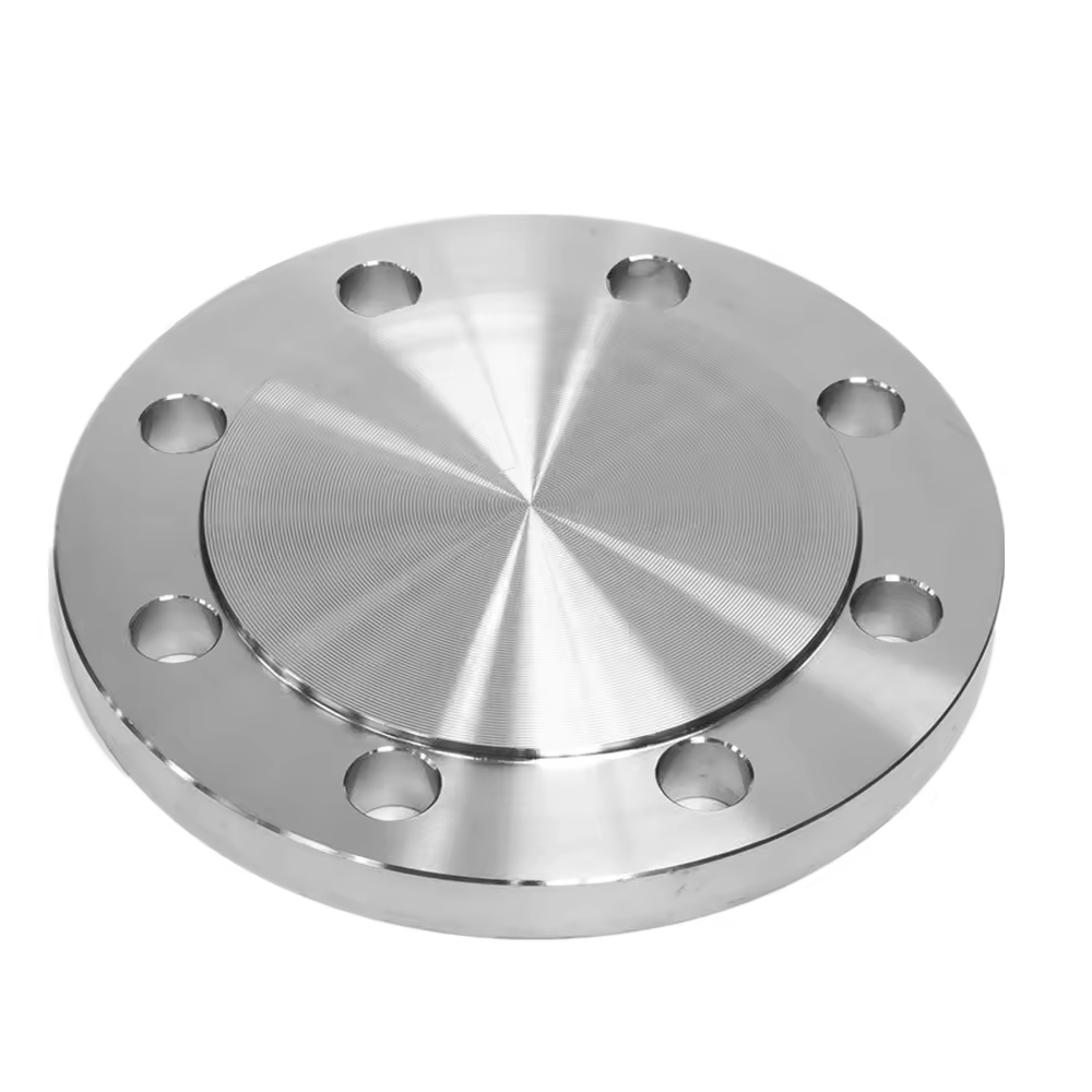
SS Blind Flange Dimensions Standard
Hot rolling primarily involves deforming the slab / bloom at high
temperature & roll
pressure - The rolling temperatures vary from 900˚C to 1200°C, which is above the
recrystallization temperature for most stainless steels.
The material runs through a series of roll with predetermined roll gaps, pressures, and
speeds to achieve its finished dimensions while being at high temperatures.
High finishing temperature ensures the production of a uniform rolled product, increases
the ability of the material to undergo thickness reductions up to 98%, and at the same
time, prevents the possibility of unwanted strain hardening. After hot rolling, the long
and thin sheets are spun into coils and left to cool, these are called Hot Rolled
coils.
Specifications
| Standard | Class | Diameter | Bolt Circle Diameter | Number of Bolts | Bolt Size | Diameter of Bolt Hole |
|---|---|---|---|---|---|---|
| AS4087 | PN14 | 95 | 67 | 4 | M12 | 14 |
| AS 2129 Flange | Table C | 95 | 67 | 4 | 13 | 14 |
| Table D | 95 | 67 | 4 | 13 | 14 | |
| Table E | 95 | 67 | 4 | 13 | 14 | |
| Table F | 95 | 67 | 4 | 13 | 14 | |
| Table H | 114 | 83 | 4 | 16 | 17 | |
| Table J | 114 | 83 | 4 | 16 | 17 | |
| ANSI B16.5 | ANSI 150 | 89 | 60 | 4 | 13 | 16 |
| ANSI 300 | 95 | 67 | 4 | 13 | 16 | |
| ANSI 600 | 95 | 67 | 4 | 13 | 16 | |
| ANSI 900 | 121 | 83 | 4 | 19 | 22 | |
| ANSI 1500 | 121 | 83 | 4 | 19 | 22 | |
| ISO 7005 (DIN) Flange | PN6 | 80 | 55 | 4 | M10 | 11 |
| PN10 | 95 | 65 | 4 | M12 | 14 | |
| PN16 | 95 | 65 | 4 | M12 | 14 | |
| PN20 | 90 | 60.5 | 4 | M14 | 16 | |
| PN25 | 95 | 65 | 4 | M12 | 14 | |
| PN40 | 95 | 65 | 4 | M12 | 14 |
SS Blind Flange Dimensions Standard
Dimensions:- ANSI/ASME B16.5, B16.28, MSS-SP-43.
| Standard | Class | Diameter | Bolt Circle Diameter | Number of Bolts | Bolt Size | Diameter of Bolt Hole |
|---|---|---|---|---|---|---|
| AS4087 | PN14 | 95 | 67 | 4 | M12 | 14 |
| AS 2129 Flange | Table C | 95 | 67 | 4 | 13 | 14 |
| Table D | 95 | 67 | 4 | 13 | 14 | |
| Table E | 95 | 67 | 4 | 13 | 14 | |
| Table F | 95 | 67 | 4 | 13 | 14 | |
| Table H | 114 | 83 | 4 | 16 | 17 | |
| Table J | 114 | 83 | 4 | 16 | 17 | |
| ANSI B16.5 | ANSI 150 | 89 | 60 | 4 | 13 | 16 |
| ANSI 300 | 95 | 67 | 4 | 13 | 16 | |
| ANSI 600 | 95 | 67 | 4 | 13 | 16 | |
| ANSI 900 | 121 | 83 | 4 | 19 | 22 | |
| ANSI 1500 | 121 | 83 | 4 | 19 | 22 | |
| ISO 7005 (DIN) Flange | PN6 | 80 | 55 | 4 | M10 | 11 |
| PN10 | 95 | 65 | 4 | M12 | 14 | |
| PN16 | 95 | 65 | 4 | M12 | 14 | |
| PN20 | 90 | 60.5 | 4 | M14 | 16 | |
| PN25 | 95 | 65 | 4 | M12 | 14 | |
| PN40 | 95 | 65 | 4 | M12 | 14 |
Stainless Steel Plate flange Pressure Rating
| ANSI/ASME B16.34 | PRESSURE RATING CHART | ||||||
| Temperature °F | 150# | 300# | 400# | 600# | 900# | 1500# | 2500# |
| -20 to 100 | 275 | 720 | 960 | 1440 | 2160 | 3600 | 6000 |
| 200 | 230 | 600 | 800 | 1200 | 1800 | 3000 | 5000 |
| 300 | 205 | 540 | 720 | 1080 | 1620 | 2700 | 4500 |
| 400 | 190 | 495 | 660 | 995 | 1490 | 2485 | 4140 |
| 500 | 170 | 465 | 620 | 930 | 1395 | 2330 | 3880 |
| 600 | 140 | 435 | 580 | 875 | 1310 | 2185 | 3640 |
| 650 | 125 | 430 | 575 | 860 | 1290 | 2150 | 3580 |
| 700 | 110 | 425 | 565 | 850 | 1275 | 2125 | 3540 |
| 750 | 95 | 415 | 555 | 830 | 1245 | 2075 | 3460 |
| 800 | 80 | 405 | 540 | 805 | 1210 | 2015 | 3360 |
| 850 | 65 | 395 | 530 | 790 | 1190 | 1980 | 3300 |
| 900 | 50 | 390 | 520 | 780 | 1165 | 1945 | 3240 |
| 950 | 35 | 380 | 510 | 765 | 1145 | 1910 | 3180 |
| 1000 | 20 | 320 | 430 | 640 | 965 | 1605 | 2675 |
| 1050 | 20 | 310 | 410 | 615 | 925 | 1545 | 2570 |
| 1100 | 20 | 255 | 345 | 515 | 770 | 1285 | 2145 |
| 1150 | 20 | 200 | 265 | 400 | 595 | 995 | 1655 |
| 1200 | 20 | 155 | 205 | 310 | 465 | 770 | 1285 |
| 1250 | 20 | 115 | 150 | 225 | 340 | 565 | 945 |
| 1300 | 20 | 85 | 115 | 170 | 255 | 430 | 715 |
| 1350 | 20 | 60 | 80 | 125 | 185 | 310 | 515 |
| 1400 | 20 | 50 | 65 | 95 | 145 | 240 | 400 |
| 1450 | 15 | 35 | 45 | 70 | 105 | 170 | 285 |
| 1500 | 10 | 25 | 35 | 55 | 80 | 135 | 230 |
ASME SA182 SS 316 Weld Neck Flange
The ASME SA182 SS 316 Weld Neck Flange and other types are used especially for the chloride ion corrosion resistance due to the addition of molybdenum in the composition. Therefore these flanges are used in marine, sea water, waste water management, pollution control, food processing, petrochemical and in oil and gas industries. The SS 316 Blind Flanges are another type of flanges used in closing a pipe line. These are useful in lines where frequent maintenance is required. The flanges have similar strength to the 304 flanges. The have 205MPa minimum yield strength and 515MPa minimum tensile strength.
Standard Specification Of A182 F316 Slip On Flange
| Specifications List | ASTM A182 / ASME SA182 |
|---|---|
| Class / Pressure Rating | 150#, 300#, 600#, 900#, 1500#, 2500#, PN6, PN10, PN16, PN25, PN40, PN64 etc. |
| Size Chart | 1/2″ (15 NB) to 48″ (1200NB) |
| ASTM Standards |
ANSI/ASME B16.5, B16.48, BS4504, B 16.47 Series A & B, BS 10, EN-1092, DIN, etc. |
| Standard Flange | ANSI, ASME, BS, DIN, EN etc. |
Flanges Pressure Rating & Flanges Standards
| ASME/ANSI B 16.5 | Welding Neck Flange, Slip on Flange, Blind Flange, High Hub Blind, Socket Weld, Lap Joint, Threaded Flange, Ring Type Joint |
| PRESSURE CLASS | 150, 300, 400, 600, 900, 1500, 2500 |
| ASME/ANSI B 16.47 | Welding Neck, Blind Flange [Series A & B] |
| PRESSURE CLASS | 75, 150, 300, 400, 600, 900 |
| ASME/ANSI B 16.36 | Welding Neck, Slip on Flange, Threaded Flange |
| PRESSURE CLASS | 300, 400, 600, 900, 1500, 2500 |
| BS 4504 SEC 3.1 | Welding Neck, Hubbed Slip on Flange, Hubbed Threaded Flange, Lapped Pipe End Flange, Plate, Loose Plate, Loose Plate With Weld Neck , Blank Flange |
| PRESSURE CLASS | PN 2.5 TO PN 40 |
| BS 4504[PART 1] | Welding Neck Flange, Hubbed Slip-On Hubbed Threaded, Plate Flange, Loose Plate With Weld On Plate Collar, Blank Flange |
| PRESSURE CLASS | PN 2.5 TO PN 400 |
| BS 1560 BOSS | Welding Neck Flange, Socket Welding Flange, Slip-On Flange, Blind Flange, Screwed Boss Flange, Lapped Flange |
| PRESSURE CLASS | 150, 300, 400, 600, 900, 1500, 2500 |
| BS10 | Welding Neck Flange, Plate Slip-On Flange, Screwed Boss Flange, Slip-On Boss Flange, Blind Flange |
| TABLE | D, E, F, H |
| DIN FLANGES | DIN 2527, 2566, 2573, 2576, 2641,2642, 2655, 2656, 2627, 2628, 2629, 2631, 2632, 2633, 2634, 2635, 2636, 2637,2638, 2673 |
| PRESSURE CLASS | PN 6 TO PN 100 |